
A transformer is an essential component of electrical power systems, which allows the safe and efficient conversion of voltages without a change of frequency. It permits the transmission of electricity produced at power plants at high voltage with low loss. In addition, it is reduces to levels useful to homes, industries, and commercial establishments. Long-distance power transmission and modern electrical networks could not exist without transformers.
From basic electrical transformer working principles to high-capacity industrial transformers, these devices operate at every stage of power generation, transmission, and distribution. The working principle, types, efficiency, and use of transformers are also important to any person in the field of electrical engineering, power system design, or industrial work.
This article describes the transformers in a simple and practical manner, encompassing working principles, calculation, loss, protection systems, and an application of the technology in the real world.
Electrical Transformer Working Principle
The electrical transformer’s working principle is based on Faraday’s law of electromagnetic induction. A transformer, when a current of alternating (AC) is passing through the primary winding of the device, an alternating magnetic flux is generates on the core. The varying magnetic field causes a voltage to induce in the second winding.
A transformer is made up of three major parts:
- Primary winding: Connected to the input AC supply.
- Secondary winding: Provides the output voltage.
- Magnetic core: Offers a low-reluctance magnetic flux route.
The induced voltage on the secondary winding is dependent on the number of turns of each winding. As, this is referred to as the turns ratio and determines whether the transformer gains or loses voltage.
Transformer operation points:
- Transformers operate on alternating current (AC).
- Primary and secondary windings have no electrical connection.
- Not direct conduction, but transferred through the magnetic field.
Due to this principle, transformers provide high efficiency, electrical isolation, and control of voltage, which makes them essential elements in the modern power system.
Step Up and Step Down Transformer Working
The main categories of transformers are defined by their operation in varying voltage levels. Step-up and step-down types are the two most prevalent types of transformers. Both use the same working principle, yet they differ in voltage and current transformation.
Step-Up Transformer Working
A step-up transformer raises the input voltage and lowers the output current. In this kind of transformer, the secondary winding will contain more turns than the primary winding.
As the primary winding is supplied with AC voltage, a magnetic flux is induced in the core. This flux is connected to the secondary winding and has a higher voltage because it has more turns.
Usually, step-up transformers are applied:
- At power generation stations.
- In long-distance power transmission.
- To minimise transmission losses
Since the power is almost constant (loss is ignored), an increase in voltage leads to a decrease in current.
Step-Down Transformer Working
A step-down transformer involves a decrease in the input voltage and an increase in the current on the output. In this design, the secondary winding has fewer turns than the primary winding.
The magnetic flux caused by the high voltage AC on the primary winding induces a lower voltage on the secondary winding because of fewer turns.
Step-down transformers are in common use:
- At distribution substations.
- In domestic and commercial power supply.
- On electronic equipment and chargers.
They are also electrically safe because they deliver usable voltage levels to the end users.
Voltage and Turns Ratio Relationship
Voltage is proportional to the turns in a transformer:
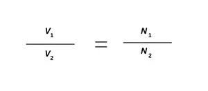
Where:
- V1 = Primary voltage
- V2 = Secondary voltage
- N1 = Primary winding turns
- N2 = Number of turns secondary winding
This equation describes the way in which transformers transform voltage without altering frequency.
Practical Applications of Step Up and Step Down Transformers
Step-up transformers and step-down transformers are both imperative in power systems:
- Step-up transformers facilitate power transmission over a long distance.
- Step-down transformers render electricity secure and accessible to consumers.
- Within complex networks, industrial transformers integrate both functions.
Efficiency, safety, and stability of the system are guaranteed by their appropriate choice.
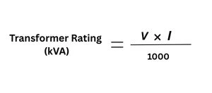
Transformer Rating Calculation Formula
Transformer rating is the maximum load that a transformer can safely carry without overheating or loss of efficiency. However, transformer ratings are given in kVA (kilovolt-ampere), rather than kW, since transformer losses are determined by voltage and current, and not by the load power factor.
Meaning of Transformer Rating
A transformer is rated in kVA since:
- Losses in copper are current-dependent.
- Core losses are voltage-dependent.
- Unknown load power factor.
KVA rating is thus a standard and a reliable method of specifying transformer capacity.
Transformer Rating Calculation Formula
The basic transformer rating calculation formula is:
To the single-phase transformer:
For a three-phase transformer:
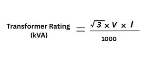
Where:
- V = Line voltage (Volts)
- I = Line current (Amperes)
Such formulas are employed in industrial and power transformers.
Factors Affecting Transformer Rating
Transformer rating depends on a number of factors, including:
- Maximum allowed rise in temperature.
- Cooling (oil-cooled or dry type)
- Insulation class
- Ambient operating conditions
Meanwhile, transformers used in industry tend to be larger than necessary so that they can cope with overloads and future growth.
Importance of Correct Transformer Rating
The selection of the right transformer rating is essential due to:
- Underrated transformers overheat and trip.
- Overrated transformers add cost and losses.
- Efficiency and life span are enhanced by proper rating.
Proper transformer rating will provide dependable operation in the power systems, substations, and industrial plants.
Power Transformer Efficiency Calculation
Power transformer efficiency is the measure of the efficiency of a transformer to convert the input electric power into useful power. Transformers are constantly running in power systems, so even a slight increase in efficiency leads to an enormous saving of energy in the long run.
Definition of Transformer Efficiency
Engineers determine transformer efficiency as a ratio of the output power and the input power. Moreover, it indicates the percentage of the electrical energy provided that they deliver to the load after including the losses within the transformer.
Mathematically:
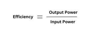
Efficiency is normally stated as a percentage.
Power Transformer Efficiency Calculation Formula
The standard power transformer efficiency calculation formula is:
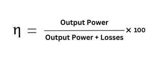
Where:
- Output Power = Load voltage × Load current × Power factor
- Losses = Core losses + Copper losses
The formula is applicable to both a single-phase and a three-phase power transformer.
Maximum Efficiency Condition
A transformer works most effectively when:
The condition normally takes place close to the rated load of the transformer. Power transformers are engineered to run near this point during most of their service life.
Factors Affecting Transformer Efficiency
Transformer efficiency is of importance as it:
- Quality of core material
- Winding resistance
- Load conditions
- Cooling method
- Operating voltage and frequency
The industrial transformers of high quality are engineered to ensure minimum losses and high efficiency in varying load conditions.
Importance of High Transformer Efficiency
Transformer efficiency is of importance as it:
- It reduces energy losses
- It lowers operating costs
- It enhances system reliability.
- It increases the life span of transformers.
Efficient transformers play a major role in the total energy conservation in big power networks.
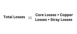
Power Transformer Losses Calculation
Power transformer losses translate the electrical energy to heat energy in the operation of transformers. Also, such losses decrease the efficiency, so designers must calculate and minimize them closely when designing and operating the transformers.
Types of Transformer Losses
Transformer losses are generically divided into two major categories:
- Core (iron) losses
- Copper losses
Other minor losses can also be experienced in some operating conditions.
Core (Iron) Losses Calculation
Core losses are caused by alternating magnetic flux in the magnetic core of the transformer. These are constant and non-load-dependent losses.
Core losses include:
- Hysteresis loss
- Eddy current loss
Core loss depends on:
- Supply voltage
- Frequency
- Core material
As such, operators can experience losses every time they energize the transformer. Thus, manufacturers construct power transformers with high-grade silicon steel cores to minimize iron losses.
Copper Losses Calculation
Copper loss is caused by resistance in transformer windings. These losses are dependent on load and are proportional to the square of the current.
Copper loss formula:
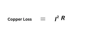
Where:
- I = Load current
- R = Winding resistance
At higher loads, copper losses grow exponentially.
Stray and Dielectric Losses
Besides core and copper losses, transformers suffer:
- Stray losses because of leakage flux inducting currents in metallic components.
- Dielectric loss in the insulation material, particularly at high voltages.
These losses are significant, however, in high-voltage industrial transformers, though minor.
Total Power Transformer Losses Calculation
The total transformer losses are determined as:
The correct calculation of loss is necessary in:
- Efficiency evaluation
- Thermal design
- Cooling system selection
Importance of Loss Calculation in Power Transformers
Knowledge of transformer losses would assist:
- Improve energy efficiency
- Reduce overheating risks
- Improve transformer life
- Optimise operational costs
One very important step in transformer selection and design of a power system is loss calculation.
Distribution Transformer Design Calculation
A distribution transformer reduces medium voltage to low voltage to allow consumers to use it directly. Unlike power transformers, distribution transformers operate 24 hours a day and remain lightly loaded, meaning that designers focus more on efficiency at partial loads.
Purpose of Distribution Transformer Design
The primary aims of distribution transformer design are:
- Very high efficiency at low and medium loads
- Good voltage regulation
- Long life cycle and low maintenance
- Consistently perform in both outdoor and urban settings
Design calculations make sure the transformer can satisfy these conditions.
Basic Design Parameters
The essential design specifications are primary and secondary voltage rates, kVA, frequency of operation, cooling mode, and insulation type. These parameters have a direct effect on core dimensions, winding configuration, thermal performance, and total losses of the transformer.
Distribution Transformer Design Calculation Basics
The calculation of design typically includes:
- Computation of core cross-sectional area
- Number of turns per volt
- Calculation of primary and secondary turns
- The selection of conductor size is dependent on current density
The per-unit voltage is determined as:
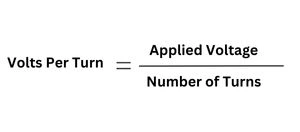
Proper calculation will make sure there is efficient use of the magnetic flux, without saturation of the core.
Load Pattern Consideration
Consideration of the load pattern is important in the design of the distribution transformers. The transformer has to work efficiently at light and average loads, and have the capacity to accommodate occasional peak loads due to the changing nature of consumer demand during the day. This is why it is more important to minimize core losses than reduce copper losses in distribution transformers.
Voltage Regulation in Distribution Transformers
Another factor of design is voltage regulation, which indicates the difference between the no-load and full-load conditions of the secondary voltage. Acceptable voltage control guarantees a stable power supply, reduces power problems, and enhances the performance of the connected equipment.
Importance of Proper Design Calculation
Accurate distribution transformer design calculation improves energy efficiency, reduces operational losses, enhances reliability, and extends transformer service life. Inappropriate design may lead to overheating, an increase in losses, volatility, and early breakage of transformers.
Power Transformer Protection System
A power transformer protection system is essential to detect abnormal conditions and prevent severe damage. Power transformers are valuable yet sensitive equipment, and therefore, any small fault cannot be tolerated as it can lead to outages, fire risks, or even failure.
Need for Transformer Protection
Some of the risks that transformers face include:
- Electrical faults
- Thermal overload
- Insulation failure
- Mechanical stress
Any kind of fault, when not properly insulated, can cause terribly disastrous damage. The protection systems provide safety and fast isolation in case of a fault.
Overcurrent Protection
The overcurrent protection protects the transformer against abnormal current as a result of short circuits, overloads, or external faults. Protective relays constantly check currents and open circuit breakers when preset thresholds are met. This is a low-cost yet functional means of protection against abnormal current conditions.
Differential Protection System
The most significant power transformer protection plan is the differential protection system. It operates by making a comparison between the current flowing into the transformer and the current flowing out of it. Any substantial variation signifies an internal defect, which causes instant separation. This system provides a quick response, a sensitive system, and dependable protection against internal transformer faults.
Buchholz Relay Protection
Relay Buchholz protection applies in oil-filled power transformers, fitting in between the main tank and the conservator. It identifies the gas build-up due to nascent faults and rapid oil flow, which is the result of serious internal breakdown. This enables early warning and tripping, and is very useful in the prevention of big damage to the transformers.
Thermal and Temperature Protection
One of the leading causes of transformer insulation failures is a rise in temperature.
Thermal protection involves:
- Oil temperature indicators
- Winding temperature sensors.
- Alarm and trip mechanisms
By these systems, overheating is avoided, and transformer life is increased.
Importance of Protection Systems in Power Transformers
A properly implemented protection system helps avoid expensive destruction, minimize downtime, increase system reliability, and increase operational safety. Protection of power transformers is thus an essential part of the modern electrical power systems.
Transformer Oil Testing Methods
Transformer oil testing methods are used to evaluate the condition of insulating oil in oil-filled transformers. Moreover, transformer oil is very crucial to insulation, cooling, and arc suppression. Hence, it should be regularly tested to maintain safe and reliable operation.
-
Breakdown Voltage (BDV) Test
The breakdown voltage (BDV) test is used to measure the dielectric strength of transformer oil. In this test, the oil in between the two electrodes is subjected to a voltage that is increased gradually until electrical breakdown occurs. High BDV value means good quality insulating material, whilst a low BDV value implies the presence of moisture, dirt, and degradation products.
-
Dissolved Gas Analysis (DGA)
One of the most significant diagnostic parameters of transformer monitoring of condition is Dissolved Gas Analysis (DGA). It monitors the gases produced by overheating, arcing, or insulation faults in the transformer. The nature and concentration of gases present are used to detect certain faults, including partial discharge, winding overheating, or intense internal arcing at an early phase.
-
Moisture Content Test
The moisture content test quantifies the level of the presence of water in transformer oil, which is typically measured in parts per million (ppm). Moisture considerably decreases the dielectric strength of the oil and increases the process of insulation aging. Such minor water drops may greatly influence the functioning of the transformers and their durability.
-
Acidity and Sludge Testing
The most commonly used types of transformers are the dry-type transformer and the oil-filled transformer. Their decision will rest on use, safety considerations, where it is fitted, and service.
Dry Type Transformer vs Oil Filled Transformer
The most commonly used types of transformers are the dry-type transformer and the oil-filled transformer. Their decision will rest on use, safety considerations, where it is fitted, and service.
Comparison Between Dry Type and Oil-Filled Transformers
| Feature | Dry Type Transformer | Oil Filled Transformer |
| Cooling Method | Air-cooled (natural or forced air) | Oil-cooled using insulating oil |
| Fire Safety | High fire safety, no oil involved | Lower fire safety due to flammable oil |
| Maintenance | Low maintenance | Requires regular oil testing and maintenance |
| Efficiency | Moderate efficiency | Higher efficiency |
| Overload Capacity | Limited overload capacity | Better overload handling |
| Installation Location | Mostly indoor installations | Mostly outdoor installations |
| Environmental Impact | Environment-friendly | Risk of oil leakage |
| Initial Cost | Higher initial cost | Lower initial cost |
| Typical Applications | Hospitals, malls, commercial buildings | Substations, industries, power plants |
Power Transformer Fault Diagnosis
Power transformer fault diagnosis involves identifying abnormal conditions inside a transformer before they lead to serious damage or failure. Reliability is enhanced, downtime is minimized, and the life of transformers is increased through early fault detection.
-
Electrical Fault Diagnosis
Electrical fault diagnosis is based on techniques like protection relay testing, insulation resistance testing, and dissolved gas testing. These techniques detect electrical issues, including inter-turn faults, phase-to-phase, and phase-to-ground faults.
-
Thermal Fault Diagnosis
Technicians detect thermal faults through oil and winding temperature control and observe the formation of gases in the transformer oil, which gives them a preliminary warning of overheating or insulation degradation.
-
Mechanical Fault Diagnosis
Engineers usually identify mechanical faults with the help of the frequency response analysis, which determines the physical alterations of windings and core structure.
Diagnostic Techniques Used in Power Transformers
Recent power transformers utilize a mix of diagnostic tools, incorporating dissolved gas analysis, turns ratio testing, insulation resistance testing, frequency response analysis, and thermal imaging. All these techniques combined assist in the identification of a developing and existing fault, allowing corrective action and maintenance to begin promptly.
Industrial Transformer Applications
Transformers used in industry will be engineered to work under high power loads, constant duty, and harsh environmental conditions. They are important in the provision of a stable and efficient power supply in different industries.
-
Power Generation Plants
In power plants, engineers employ transformers to scale up generated voltage for long-distance transmission, interconnect generators to transmission systems, and generally stabilize the operation of the entire system. The voltage of these transformers is very high, and designers create them to be highly efficient and reliable.
-
Manufacturing and Heavy Industries
Industries and heavy manufacturing industries like steel plants, cement plants, chemical processing plants, and automobile manufacturing plants use industrial transformers to deliver power to heavy machinery, furnaces, motors, and automated production systems. Such applications have a need for constant voltage, high power capacity, and a constant power supply.
-
Substations and Power Distribution Networks
Transformers in substations and power distribution networks reduce the voltage used in transmission to distribution levels, regulate voltage, and turn power flow between networks. Power and distribution transformers efficiently cooperate to deliver safe and efficient electricity to the end users.
-
Renewable Energy Systems
Renewable systems, such as solar power stations, wind farms, and hydroelectric stations, also require the use of industrial transformers. They ensure that the voltage levels of renewable energy sources are equal to those of the electrical grid by facilitating compatibility of power.
-
Transportation and Infrastructure
Moreover, the transportation and infrastructure programme (rail, metro, airports, ports, large commercial complexes) also uses transformers. Such applications require reliable use, constant use, and high resistance to electrical failures.
Conclusion
In the present electric power systems, a transformer is a very significant element that aids in an efficient conversion of voltages, electrical isolation, and safe transmission of power in networks. With the knowledge of step-up and step-down operation, transformer rating and efficiency calculations, fault diagnosis, periodic tests, protection, and proper selection, the electrical infrastructure has become a dependable workhorse with transformers, resulting in minimal losses, high efficiency, and long life.
1 Trackback / Pingback